Below is a list of archival equipment at the Ionosphere Research Building of Manila Observatory with their one paragraph descriptions. Most of the pictures can be found in the references. Notice that the equipment span more than 40 years, starting from 1952, which is a year after the Observatory decided to leave most of the meteorological work to the government’s new Philippine Weather Bureau and move to Mirador in Baguio City to focus more on seismology and space weather.
1. Model 200CD Wide Range Oscillator (1952)
An audio oscillator is an instrument that generates one pure tone or frequency at a time. Through the years, HP oscillators were used to design, produce and maintain telephones, stereos, radios and other audio equipment. / The Model 200CD and its sister instrument, the Model 200AB, were introduced at the same time in 1952. These new oscillators represented a substantial increase in versatility over previous ones. For example, the frequency range of the 200CD (5 cps to 600 kc) was such that it replaced two of the older HP oscillators, Models 200C and 200D, which were discontinued. This was accomplished without an increase in price. The wide frequency coverage made this instrument very valuable as a general purpose oscillator. / In addition to advances in electrical design, the cabinetry of the new oscillator was redesigned. The cabinet width was reduced to save bench space, while the appearance was designed to be more pleasing and to aid in operation. One of the improvements was a large, 6-inch tuning dial. / The 200CD was used for testing servo and vibration systems, medical and geophysical equipment, audio amplifiers, sonar and supersonic apparatus, carrier telephone systems and video frequency circuits.
Reference: HP Virtual Museum
2. Berkeley Universal Counter and Timer Model 5510 (~1955)
Frequency was read from a Berkeley Universal Counter and Timer, Model 5510, This counter could also be connected to the sound generator to read the frequency of the forcing function.
Reference: Y. C. Fung, A. Kaplan, and E. E. Sechler, Experiments on the vibration of thin cylindrical shells under internal pressure, Report No. AM 5-9, The Ramo-Woolridge Corporation, Guided Missile Research Division, Aeromechanics Seciton, 15 December 1955, pp. 2 (of pdf)
Note: See also Edmund Klemmer, Simple reaction time as a function of time uncertainty, Journal of Experimental Psychology, vo. 54, no. 3, 1957.
3. Schonstedt Magnetometer (1959)
Cylindrical core magnetometers have been constructed by Schonstedt (1959) and Primdahl (1970). The Schonstedt sensors consist of a ceramic cylinder with thin Permalloy tape helically wound around the cylinder, thus the name HELIFLUX sensor. The drive winding is applied toroidally through the tube with solenoid feedback coil around the tube. This HELIFLUX sensor resulted in low noise and stable offsets, it was used on a number of space flights.
Reference: Gunter Musmann (ed.), Fluxgate Magnetometers for Space Research, pp. 138-139.
4. Tektronix Type 535A Oscilloscope (1959)
The Tektronix Type 535A is a DC-to-15 MC Oscilloscope with a wide range of sweep delay. It is easier to operate and offers higher performance than its predecessor, the Type 535. Color-correlated controls contribute greatly to ease of operation. Other contributing factors to easy operation of the Type 535A are simplified panel layout and horizontal display control, single-knob sweep and calibrator controls, and internal triggering for sweep delay. Greater reliability has been achieved through use of the new frame-grid twin triodes, and a change to silicon diodes in the power supplies. Performance improvement includes an extra 5 mc in vertical response and wider range of sweep delay.
Reference: Radio Museum.
5. JMR-1 Doppler Survey Set (~1970s)
Shortly after the former Soviet republic launched its first Sputnik satellite in October 1957, its orbit was accurately determined by measuring and analyzing the Doppler frequency curve from a single satellite pass. Shortly thereafter, the U.S. Navy navigation satellite system (NNSS) was conceived….
The Doppler NNSS [Navy Navigation Satellite System] became available for civilian use in 1967, when details of receiver equipment and computation requirements were made public. Until then, usage had been restricted primarily to the navigation of U.S. Navy vessels. Although the control surveying potential of the transit system had been demonstrated, applicable Doppler receiver equipment was bulky with complex field operation and data-reduction procedures. But portable geodetic receivers were developed and available for testing by the early 1970s (see Figure 14-16 [JMR-1] and 14-17). Initial results indicated that accuracies better than 1.5 m were possible, thus making many geodetic applications feasible.
Reference: Russel C. Brinker, Roy Minnick, The Surveying Handbook, p. 320.
6. Tektronix Type 7633 Oscilloscope (1977-1989)
The TEK 7633/R7633 storage oscilloscope is a solid state instrument especially designed for fast writing rate storage applications. The 7633 Storage Oscilloscope Mainframe provides a 100MHz, three compartment mainframe for the wide range of Tektronix 7000-Series plug-ins. The instrument has three display modes and four storage modes. The maximum writing speed of 1000cm/us is achieved in reduced scan mode.
Reference: Barry Tech.
7. Ionosonde Type 4B (~1993)
The general purpose of this equipment is to sound the ionosphere at regular intervals by the pulse-echo technique at vertical incidence, and to plot the relationship of the virtual height of reflection of the pulse echoes against the transmitted frequency. The operating frequency of a pulsed transmitter is varied over the range 1 MHz to 22.6 MHz. The resulting echoes from the ionosphere are then detected by a receiver tuned, automatically, to the same frequency as the transmitter. The echoes received are processed to remove noise and interference and are displayed on a cathode ray tuebe along with a graticule indicating virtual height along one axis and frequency along the other. The trace is then photographed by an automatically operated camera, and the records produced are called ionograms. From these records and the necessary ionospheric data are obtained and used for prediction and research purposes.
Reference: Ionosonde Type 4B Handbook (Complete and Unmarked), Section 1.1.
Note: Check out also the Handbook 3 of 3 of the Ionosonde Type 4B/D, Unix Control and Communications Computer for IPS Ionosonde 4D.
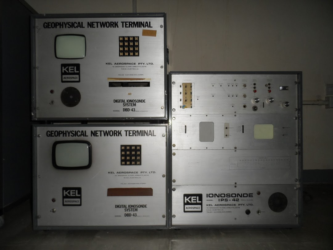
8. KEL Ionosonde IPS-42 / DBD-43 (1994)
The KEL ionosonde is used to measure the virtual height and critical frequency of the ionosphere. The Digital Ionosonde System (KEL Aerospace Pvt Ltd, Australia), installed at Waltair in the year 1989, consists of an IPS-42 (Ionospheric Prediction Service) ionosonde and an DBD-43 system dedicated to the IPS-42 with pre-programmed software, a double delta antenna and a hard copy printer. The IPS-42 consists of a transmitter, receiver and all necessary sub-systems. The DBD-43 is used for controlling the operational program of IPS-42, i.e. to store and scale the ionograms and to give commands for the printouts.
Reference: P. L. Saranya, D. S. V. V. D. Prasad, K. Niranjan, and P. V. S. Rama Rao, Short term variability in foF2 and TEC over low latitude stations in the Indian sector, Indian Journal of Radio and Space Physics, vol. 44, March 2015, pp. 14-27.